FRIEX : New friction welding method for automatic welding of pipelines
Project goals
To enable pipelines to be welded using friction welding, a new variant of the conventional process has been developed, which is called “FRIEX”. The major difference of the new variant with conventional friction welding is that a “filler material” in the form of a solid ring is used. The welding ring is placed in between the pipes, and rotating the ring under an axial pressure generates the required friction and associated heat.
Project description
Working principle of the Friex-process
The Friex welding process is based on the friction welding process. This is a forge welding process in which the heat necessary to realise the weld, is generated as a result of the friction forces between two surfaces rubbing against each other under controlled axial pressure. The relative motion or rubbing of the two parts is continued until sufficient heat has been generated. Then the rubbing is stopped and the two pieces are forged. Most applications involve welding of round or cylindrical parts, because friction can simply be generated by relative rotation.
The disadvantage of the friction welding process is that it is impossible to weld parts that cannot be rotated. This is also the case for pipelines, since the pipe sections can be as long as 18 meters. In order to be able to use the friction welding process for pipeline welding anyhow, a new variant has been developed, called the Friex-process.
The major difference of the new variant with conventional friction welding is that a filler material in the form of a solid ring is used. This welding ring is placed in between the pipes, and rotating the ring under an axial pressure generates the required friction and associated heat (see Figure below).
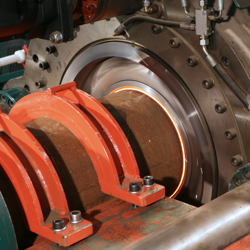
After the components are brought into contact, the friction between the rotating ring and the pipes increases the temperature in the contact areas, until the forge temperature is reached. At that moment, the rotation of the ring is rapidly stopped, and the axial force is increased to the final forge force. Forging is done using an "explosive" force (either hydraulic or pneumatic). After welding, the remaining welding ring material and welding flashes are removed using an automated milling mechanism.
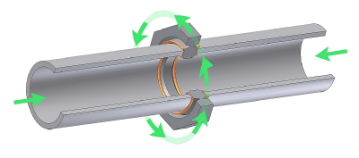
Figure : Principle of the new welding process
The FRIEX welding process thus consists of four distinct phases:
- The work pieces approach the welding ring.
- The work pieces are brought in contact with the welding ring, and the rotation of the ring is started.
- The axial pressure is increased, which causes the temperature to rise, until the forge temperature is reached.
- The rotation of the welding ring is stopped, and the final forge force is applied.
During the second phase (phase of dry friction), the components are in contact at an initial low axial contact pressure to clean the butting faces, achieve some pre-heating and reduce the coefficient of friction before the pressure is increased. During this phase, considerable power is required to rotate the welding ring, since the friction torque can be quite high. An initial low contact pressure is used in order to prevent stalling of the drive motor. The initial stage continues for a predetermined time.
During the third phase, the axial force is raised to increase the friction between the components. The pipe and welding ring material plasticise and flow out, to form the characteristic "flash". The displacement of material (usually called "burn-off") ensures that contaminants are removed from the weld interface. The end of this stage is usually controlled when a pre-set shortening is reached. At the end of this stage the rotation is stopped as rapidly as possible.
During the 4th and final phase, the axial force is increased to forge the components. This stage provides additional mechanical working of the joint with no heat input and thus promotes refinement of the microstructure. At the end of this stage the weld is completed, and ready for removal of the welding flashes and the remnants of the welding ring.
Advantages
The FRIEX concept claims a series of advantages over traditional arc welding.
- Consistent high quality of weld. There are increasingly stringent quality requirements on pipeline welds. Automatic welding is offering a solution for this. With automatic welding, the welder performs the role of a welding machine operator. The quality of the joint therefore depends on the one-time setup of the welding machine. FRIEX offers the capability of delivering consistent quality, weld-after weld.
- Fully automated high-speed process. There is a rising difficulty to find skilled welders and to dispatch them to often remote and inhospitable areas. By using an automated technology-driven process the need for having welders on site is less stringent (only for occasional repair work). Moreover the welding speed of the one-shot Friex technology is a multiple of what manual or semi-automatic can offer today. Friex is also tolerant to significant variations in process parameters (speed,reliability, …)
- Low cost. Unlike arc welding, there is only minimal joint preparation and post-treatment needed. In addition there are no fluxes or shielding gases required. There are less process steps, implying significant cost savings. Equipment is limited and results in low maintenance cost.
- Health, Environment & Safety. Friex is environmentally friendly and safe, as no harmful fumes are generated. There is a narrow heat affected zone, because of the short welding times and the relatively low temperatures, resulting in better welding accuracy, toughness and lower material fatigue. The shorter welding time makes FRIEX use less energy and therefore emit less CO2.
- Ability to deal with high strength steels. There is an increasing end-user driven demand for high strength (multi-phase) steels for pipeline applications. These steel grades typically are more difficult to weld with conventional technologies.Pipeline steel has a low carbon content (typically < 0.09%) and is micro-alloyed. In order to achieve its high strength, it undergoes various thermomechanical treatments. When welding, there is deposit of heat that can negatively impact the strength of the pipe structure in the heat affected zone. FRIEX is a solid state process without melting. There is a narrow heat affected zone, because of short welding times and the relatively low temperatures, resulting in better welding accuracy, toughness and lower material fatigue. In addition, porosity and slag inclusions are eliminated.
Results
Process development
The Friex technology has been investigated in an incremental way over the past years. The development was performed as a cooperation between the company DENYS NV, the Belgian Welding Institute (BWI) and the University of Ghent; laboratory Soete(LS).
FRIEX - Phase 1
In a first phase (Friex I, 1998 - 2001), a first small-scale welding machine was developed to establish a proof-of-concept, based on limited-diameter pipes (typically 50 mm outside diameter). The material used was plain carbon steel. The process parameters for welding these kind of pipes were optimised. The quality of the resulting welds was assessed by metallographic examination and mechanical testing. As a result of this phase, the weldabilty of plain carbon steel pipes with the Friex-process was demonstrated.

Figure : Small-scale test set up
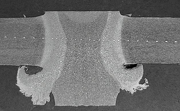
Figure : Macroscopic section of a weld

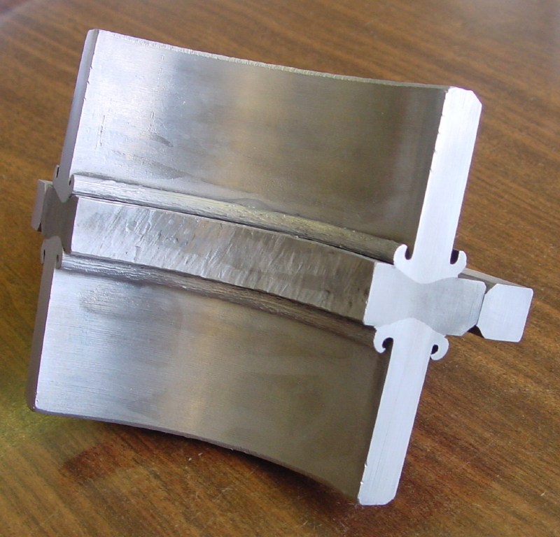
Figure : Typical small-scale weld
FRIEX - Phase 2
During Friex II (2001 - 2003), a new test equipment was constructed to allow welding trials with larger diameter pipes, up to 114 mm outside diameter (4 inch). The materials investigated were the carbon steel grades S355 and API-5L X42. During this phase, it was demonstrated that the weld quality in general, and the impact toughness in particular, was highly dependent on the process parameters (thickness of the welding ring, rotation speed, process duration, forging pressure, …). The parameters have to be set within a “welding window”. In-depth research was performed on establishment of these parameter windows; a challenging assignment since every individual parameter has an influence on the weld quality and because the single parameters are influencing each other as well.
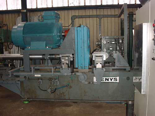
Figure : Medium-scale test set up
|
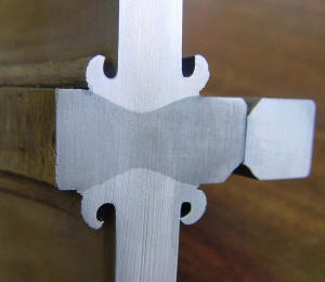
Figure : Typical medium scale weld |
Figuur : Detail of previous figure |
Numerical modelling of the process
In addition, a first concept was designed for flash removal after the weld cycle.
There was also a modelling effort, based on finite-elements analysis techniques, to describe the friction welding processes for different product forms (diameters, various steel alloys, …) in terms of temperature distribution, heat fluxes, plastic deformation, etc. This was executed by the University of Graz (Austria), based on input data, registered during and after the welding tests. These models allowed to predict the deformation behaviour and temperature fields during welding.
 |
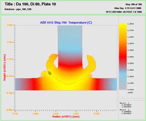 |
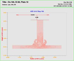
Figure : Finite-element simulation (T.U. graz)
FRIEX - Phase 3
In a third phase, Friex III (2004-2007), several key topics for the further development and understanding of the technology were investigated. A first subject was the investigation of the feasibility of welding high-strength steels. So far the tests were performed on conventional C-Mn-steel grades in the normalised condition. In the 3rd phase micro-alloyed low carbon steel of grade API-5L X70 was also investigated.
Moreover, the FEM models were further refined with a new partner, Cenaero of Charleroi, Belgium. This was helpful to design the optimal form and size of the welding ring, to extrapolate the test results towards larger dimensions and to assess the influence of the modified relation between the pipe thickness in relation to the outside diameter. The resulting FEM models from Graz University and Cenaero enable to predict welding parameters, reducing the need for extensive testing. More underpinned decisions could be made for the design of actual welding tests.
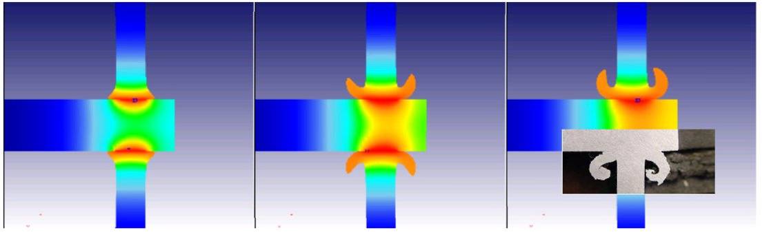
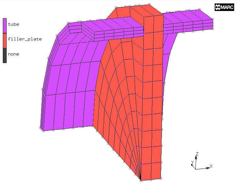
Figure : Finite-element simulation of the process (Cenaero)
A 3rd aim of this project phase was the investigation of the influence of the welding parameters (forging pressure, friction pressure, rotation speed, welding time, dimensions of the welding ring, forced cooling, etc.) on the characteristics of welded API-5L X42 and X52 pipes. For example, the influence of the welding ring thickness is shown in the figure below.
The major results of the investigations on X42 and X52 pipes are summarised in the papers :
- K. Faes, A. Dhooge, O. Jaspart, L. D'Alvise, P. Afschrift, P. De Baets. New friction welding process for pipeline girth welds - parameter optimization. Proceedings of the Institution of Mechanical Engineers, Part B: Journal of Engineering Manufacture, Vol. 221, No. 5, 2007, May 2007, p. 897 - 907 (link).
Selected by the Editor and a subcommittee of the Editorial Board to receive the PE Publishing Award for the best paper published in 2007. - K. Faes, W. Vermeirsch, P. De Baets, R. Denys, E. Van Der Donckt. Influence of forge pressure on properties of friction welded pipelines using intermediate ring. Science and Technology of Welding & Joining 2008, Vol. 13, nr. 5, April 2008, p. 445 - 451 (link)
- K. Faes, A. Dhooge, P. De Baets, P. Afschrift. Influence of deceleration phase on properties of friction welded pipelines using intermediate ring. Science and Technology of Welding & Joining, Volume 13, No. 2, Febr. 2008, p. 136 - 145 (10) (link)
- K. Faes, A. Dhooge, P. De Baets, E. Van Der Donckt, W. De Waele. Parameter optimisation for automatic pipeline girth welding using a new friction welding method. Materials and Design 30, 2009, p. 581 - 589 (link).
- K. Faes, A. Dhooge, P. Afschrift, P. De Baets. New friction welding process for pipeline girth welds - welding time optimisation. Int. Journal of Advanced Manufacturing Technology, Vol. 43, p. 982 - 992, 2009 (link).
Design of a large-scale test installation
Also a design of a large-scale test installation was drafted for an operational field machine with capabilities for welding steel pipes with a diameter of 8 to 20 inch (O.D. : 219,1 and 504 mm). Various technical aspects of a field operation were investigated, such as the necessary drive torque, power capacity, clamping methods for coated pipes, axial forces between welding ring and pipe, fixture of the welding ring, internal clamping, removal of welding flashes, forging forces, etc.
Large-scale tensile test installation
Initial steps were taken in the area of welding qualification, such as the design and the construction of a large-scale tensile test installation and the preparation and construction of a large-scale welding installation at Denys.
- More information here

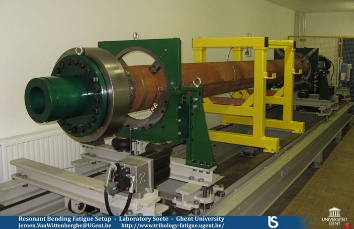
Full scale resonant bending fatigue test setup
To test pipe joints in pipes with a diameter up to 20 inch, a new full scale resonant bending fatigue test setup was developed at the Laboratory Soete.
In the setup the test pipe with a central joint is excitated by a drive unit with eccentric masses. The central section of the pipe will be subjected to the highest bending loads during the fatigue test.
- More information here
Friex - Phase 4
Preparation of the qualification by large scale welding experiments
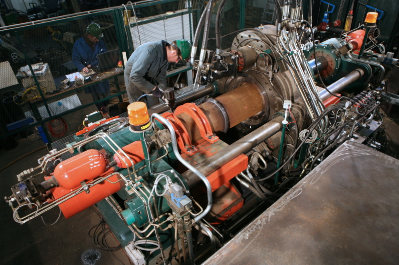
In phase 4 of the investigation, the process was scaled up to larger diameter pipes, in order to evaluate the weldability of high strength micro-alloyed pipeline steels, such as API-5L X60, X70 and X80. A large-scale test set-up for joining pipes up to 20 inch (O.D. : 504 mm) in diameter was designed and built.
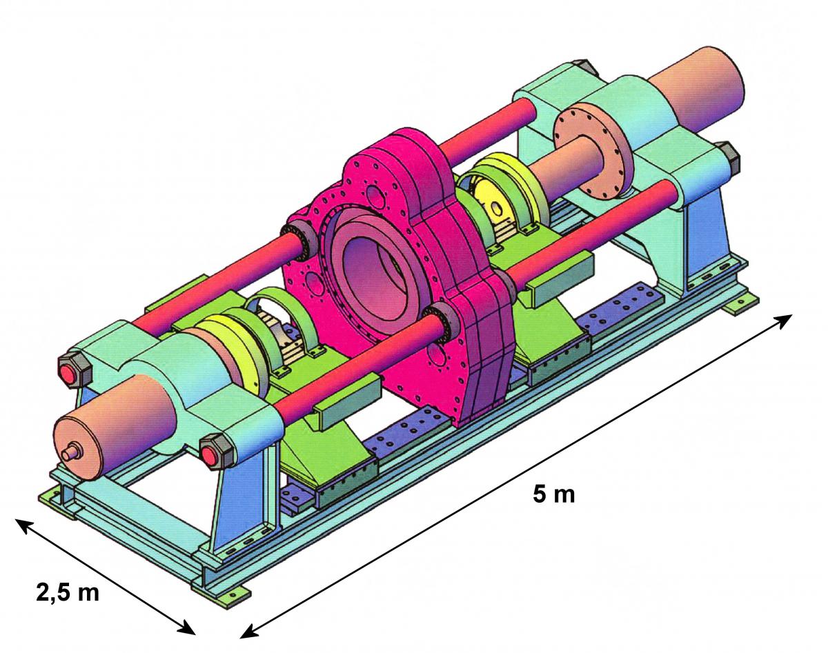
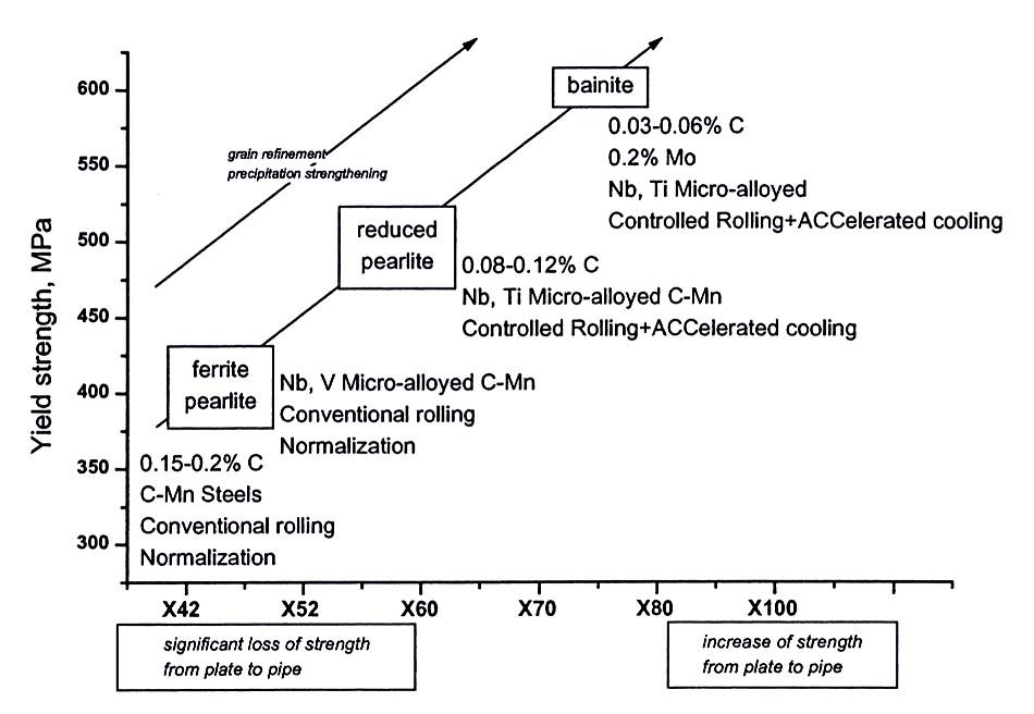
Figure : Schematic overview of existing pipeline steels, together with the fabrication processes and microstructures to achieve the desired strength and toughness
The welding machine is suitable for welding pipes with a diameter of 8 up to 20 inch. The rotation of the welding ring is realised using 6 hydraulic motors, each connected to a planetary gear system, which are in their turn mounted on a central placed large gear transmission. The welding ring is mounted in the large hollow gear wheel of the gear system, in a rigid clamping device able to transmit the drive power and torque. The maximum rotation speed of the welding ring is 250 rpm. The available effective drive power and torque equals resp. 600 kW and 100.000 Nm.
 |
|
Weldability of the pipeline steel API-5L X65 (L455QB)
For investigating the feasibility of the use of the new welding process for joining high-strength micro-alloyed pipeline steels, exploratory welding trials were performed with the quenched and tempered micro-alloyed high-strength pipeline steel API-5L X65.
All details can be found in the publication :
- K. Faes. P. De Baets, W. De Waele, E. Van Der Donckt, D. Delbaere. New friction welding process for pipeline girth welding: Weldability of micro-alloyed high-strength pipeline steels. Proceedings of the Pipeline Technology Conference, 12 - 15 Oct. 2009, Oostende, Belgium.
The weld quality was assessed based on metallographic examinations, tensile, bending and Charpy impact testing.
The tensile test specimens made from the welds fractured in the pipe base material, at a tensile strength equal to the pipe base material tensile strength. All bending test specimens could be bent to an angle of 180° without fracture.
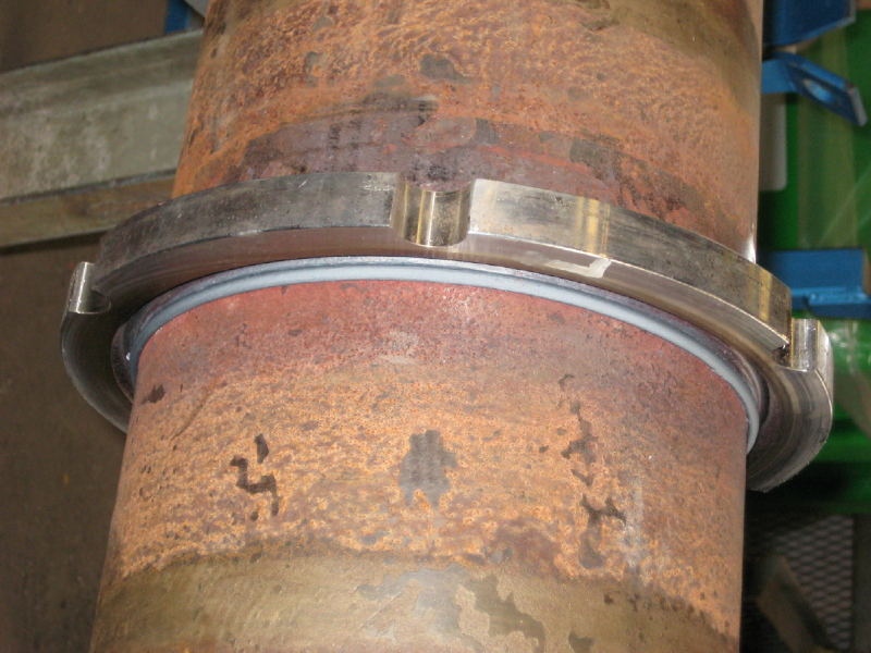
Figure : Weld of 8 inch pipes (O.D. : 219 mm) in the as-welded condition
For each weld 3 sets of at least 6 Charpy impact tests were carried out. Three types of test specimens were used, based on the position of the notch (in the middle of the welding ring, or at the left or at the right weld interface). In EN 12732 an average impact energy of 40 J is required, with the individual values not lower than 30 J for steel grades with a specified minimum yield stress higher than 360 MPa. The testing temperature was equal to -20°C.
The impact toughness of the investigated welds is shown in the figure below as a function of the total heat input. At the weld interface, the impact toughness is high for the lowest heat input. The impact toughness decreases for a higher heat input. The impact toughness measured in the middle of the welding ring is always high and not dependent on the heat input.
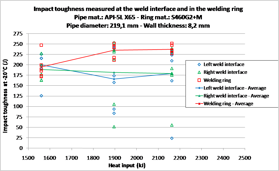
Figure : Charpy impact toughness as function of the heat input
In the pipe HAZ of all welds, the hardness decreases slightly below the base material hardness value (193 HV1), at 2 to 6 mm from the weld interface (see figure below). Also in the welding ring HAZ softening is observed (hardness ring base material: 196 HV1). The width of the softened zone decreases for a lower heat input. Weld 3, executed with the lowest heat input, contains the smallest softened zone. Also the hardness decrease is minimal for this weld. The decrease of the hardness is however not detrimental to the weld strength; since all tensile test specimens broke outside of the weld zone.
The weldability of this pipe material was thus successfully demonstrated and opens promising perspectives for the weldability of the higher strength pipeline steels.

Figure : Hardness profile of the investigated welds
- More information about the weldability of this pipeline material using the FRIEX process can be found here.