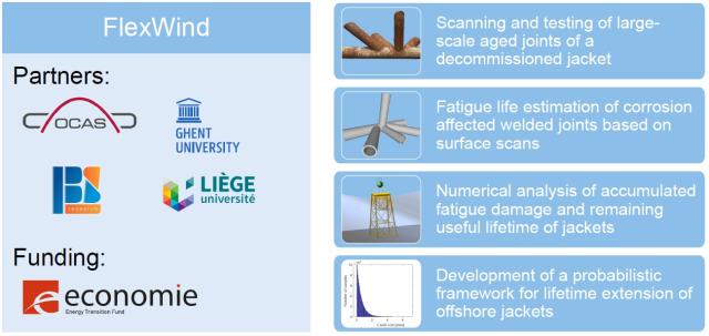
FlexWind: Fatigue Life EXtension of offshore Wind foundations
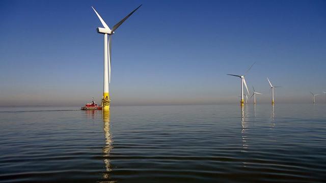
Offshore wind turbines and their foundations are designed for a lifetime of 20 to 30 years. Once this design life has passed, the standard procedure is that the operation of the structure can be prolonged if it is shown that the loading was lower than anticipated during the design phase. This is only possible if accurate monitoring has been performed, and it also neglects the possibility that the structure has actually a larger fatigue resistance than assumed in standards.
Project goals
In the FlexWind proposal, we will investigate the possibility to prolong the life of an aged offshore foundation of an offshore wind turbine by re-assessing the fatigue resistance of critical joints of the substructure. To this end, welded joints, including decommissioned node joints, are scanned and subjected to fatigue tests to understand the relationships between scan data and fatigue behaviour. These data are then modelled to determine a residual life. This will be done by innovative methods combining:
- inspection of aged joints (scanning the geometry of critical joints, assessment of the surface degradation due to corrosion),
- numerical analysis of accumulated fatigue damage (backward modelling) and remaining useful lifetime (forward modelling),
- probabilistic tools to account for the inherent stochastic nature of a wide range of parameters affecting fatigue resistance,
- representative experiments on aged large-scale joints of offshore jackets.
The Belgian Welding Institute will carry out laser scanning of welds as well as fatigue tests on welded joints within the project.
Project description
Experimental characterisation
This work package is dedicated to systematically investigating the fatigue properties of welded joints, emphasizing the influence of welding parameters, surface degradation and environmental conditions. The experimental approach includes the preparation and testing of both small- and large-scale samples:
- Sample preparation: Small-scale welded samples are produced to explore the effects of welding processes (MIG/MAG and submerged arc welding) on the weld topology and mechanical properties. Imperfections are deliberately introduced to study their impact on the fatigue performance. Additional small-scale samples will simulate "pre-fatigued" conditions representative of actual service environments, and large-scale samples, preferably obtained from decommissioned offshore structures, will provide insights into the fatigue behavior under realistic conditions.
- Weld geometry and corrosion characterisation: Advanced laser scanning systems (line, 3D handheld and coordinate measurement tools) are deployed to accurately map the weld topologies and the surface degradation caused by corrosion. The data is processed to establish standardised definitions and identify critical weld geometry features influencing the fatigue life.
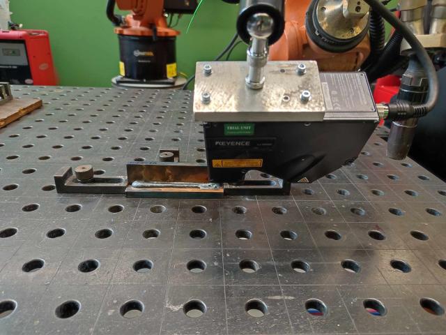

Laser scanning of welds
> More information on laser scanning of welds
- Destructive and non-destructive testing: Both untreated and pre-fatigued samples undergo rigorous testing, including visual inspection, metallography, hardness measurements and mechanical testing (tensile, bending and impact). These tests aim to assess the internal weld quality and determine the fatigue performance, particularly in the crack initiation and early propagation stages.
- Large-scale sample testing: A representative large-scale welded joint is subjected to fatigue testing to address scale effects. If possible, a sample from a decommissioned structure is used, offering practical insights into the performance of in-service welds.
Large-scale welded welded tubular joints from a decommissioned jacket structure which served over 30 years in the North Sea will be tested to determine the actual remaining life. After the jacket structure had been brought to shore, OCAS went to the decommissioning yard to mark the locations to cut the samples. The sampled tubular joints are scanned using a 3D scanner and the scanned data is further processed by UGent.
The samples will be subjected to resonant bending fatigue tests performed by OCAS. The obtained fatigue results will be compared to remaining lifetime predictions.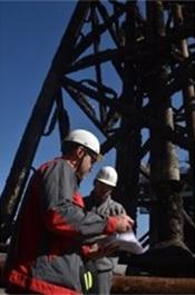
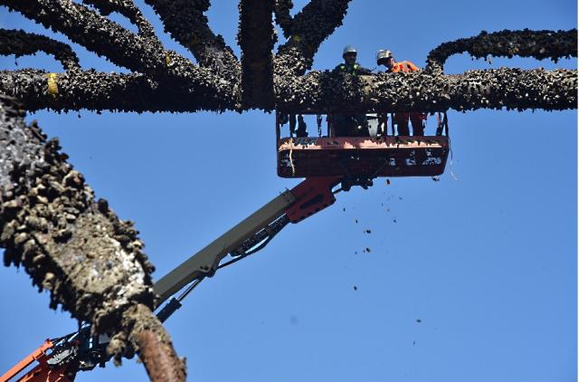
Marking of the large-scale tubular joints at the decommissioning yard.
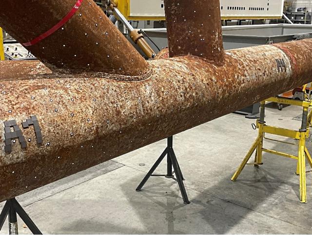
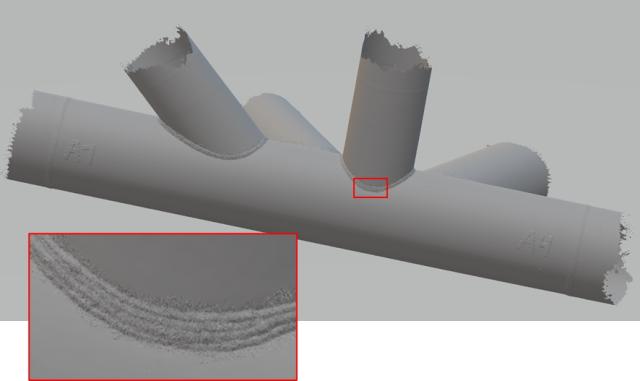
Setup for 3D scanning of the large-scale samples and scan result.
- Post-weld treatment investigation: Techniques such as TIG dressing, plasma dressing and pneumatic impact treatment (PIT) are evaluated for their effectiveness in enhancing fatigue resistance by addressing weld toe geometry or inducing beneficial residual stresses.
The deliverables include experimentally prepared samples, extensive reports on weld properties and performance and recommendations for fatigue optimisation.
Fatigue life estimation based on surface scans
This work package focuses on the development of computational methods to estimate the fatigue life of welded joints, considering real-world factors such as weld imperfections and corrosion. This work package integrates experimental data with predictive analysis tools using advanced numerical modeling.
- Automated model ceation: Algorithms are developed to convert 3D scanned weld geometries into high-fidelity finite element (FE) models. These models capture realistic weld geometries, including misalignments, corrosion effects and weld root characteristics, often neglected in idealised simulations. The framework ensures full automation, enabling efficient analysis of large datasets.
- Stress gradient method development: A new fatigue analysis method is created to assess the influence of the weld geometry and corrosion-induced imperfections on stress distributions and concentration factors. The method accounts for complex notch effects and surface degradation, providing an accurate representation of fatigue behavior under real-world conditions.
- Impact of surface state on on the stress concentration factors: Numerical studies investigate how surface degradation, captured via scans of decommissioned or experimentally treated samples, changes stress concentration factors. This enables a deeper understanding of how imperfections and wear affect the fatigue life.
Deliverables include a robust method for generating FE models from scans, a validated stress gradient analysis framework and insights into the role of surface degradation in fatigue performance.
Hindcasting and forecasting fatigue life
This work package aims to integrate experimental and numerical tools to predict the accumulated fatigue damage and the remaining life of offshore welded joints, leveraging advanced simulations of environmental and operational conditions.
- Multi-level modeling framework: The work package connects global structural models with localised submodels, facilitating detailed analysis of weld joints while considering the overall structure's behavior. Using tools like Qblade, environmental loads on offshore wind turbines (OWTs) are simulated, providing inputs for joint-level stress analysis.
- Environmental and operational simulations: Time-domain simulations are conducted to capture the effects of varying environmental conditions and operating loads. These simulations generate realistic load spectra, enabling accurate fatigue assessments.
- Fatigue assessment: The localized stress spectra derived from submodels are used to evaluate accumulated damage and forecast remaining fatigue life. This involves both hindcasting (retrospective analysis) and forecasting, enabling a full lifecycle assessment of weld joints.
- Validation: Numerical tools are rigorously compared against experimental data from the first work package, ensuring accuracy and reliability for industrial application.
Deliverables include an integrated simulation model, a method for analyzing fatigue based on interface loads, and a comprehensive database of fatigue life results.
Probabilistic framework for lifetime extension
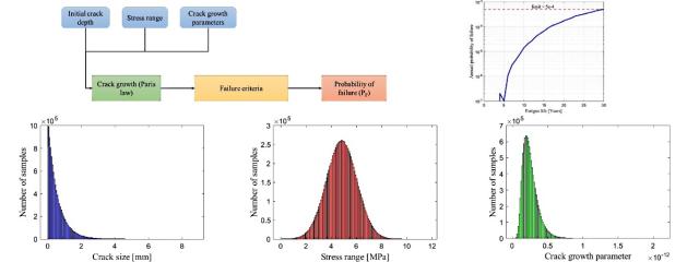
This work package focuses on developing a probabilistic approach to extend the operational life of offshore structures, incorporating uncertainty quantification, system-level reliability analysis and cost-benefit evaluation. To quantify the uncertainty on fatigue life predictions ULiège employs advanced statistical methods. The goal is to get a robust understanding of factors influencing the fatigue degradation model. A fracture mechanics based deterioration model is used for this.
- Uncertainty quantification: Probabilistic models assess the variability and sensitivity of fatigue-related parameters, using data from experimental (WP1) and numerical (WP3) studies. Techniques like Monte Carlo simulations and sensitivity analyses identify key factors influencing fatigue predictions.
- System-level reliability analysis: The updated fatigue parameters are used to calculate the failure probability of entire structures, rather than individual joints. This system-level approach ensures decisions reflect the broader implications of structural failure.
- Decision-making framework: A comprehensive methodology evaluates the costs and benefits of life extension options, including maintenance, repair, decommissioning, and operational costs. Uncertainties in these costs are also accounted for to support robust, informed decision-making.
Deliverables include detailed models for uncertainty quantification, methodologies for system-level reliability analysis and an optimal decision-making framework for life extension planning.
Conclusions and guidelines
The final work package consolidates results from all other work packages into actionable guidelines for extending the life of offshore wind turbines.
- Technical guidelines: The guidelines will integrate findings from experimental, numerical and probabilistic studies, providing a roadmap for assessing and optimising OWT lifetime extension.
- Broader considerations: Recommendations will address regulatory requirements, environmental impacts and stakeholder interests, ensuring a holistic approach to decision-making.
The deliverable is a comprehensive report outlining best practices, methodologies and considerations for planning OWT life extensions.
Results
Experimental characterisation
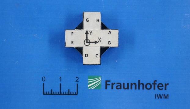
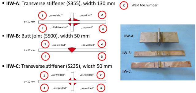
For laser scanning of welds, there is no universal agreement on the definition of geometry parameters or on standardized measuring routines. To address this and evaluate the techniques used across research laboratories, a comprehensive round robin study was conducted over the past years, with contributions from BWI, OCAS and Labo Soete.
Participants were assigned two measurement tasks:
- Part A: Analyze a machined specimen with a well-known geometry inspired by a cruciform joint. Results were compared to the actual dimensions of the specimen.
- Part B: Measure welded specimens with unknown geometry, with the results benchmarked against those of other participants.
This article focuses on summarizing the findings from Part A.
Publications
- FlexWind veut prolonger la vie des éoliennes - Le Soir
- Presentation BIL Lassymposium
- EAWE Seminar on Wind Energy – Extended abstract
- Round robin study on the determination of weld geometry parameters - Part A: analysis of a reference specimen
- Remaining fatigue lifetime of welded tubular joints of offshore structures using detailed stress analysis based on 3D scans
- Converting laser scans of tubular joints to finite element models for detailed stress analysis